This is the story of how an ‘electronics-engineer-turned-UX-designer’ built a microcontroller circuit with his kids after a twelve-year hiatus from the world of electronics. Let us begin by going back 30 years into the past…
A 12-year-old Electronics Hobbyist
Early 1990s. I was in seventh standard at a school in our small town. One day my friend Shihab, who lived nearby, came to my home carrying a magazine ‘Electronics for Everybody’ in Malayalam language. It featured hobby circuits, articles on basic principles of electronics, ham radio, contact details of electronics parts suppliers…
The magazine Shihab brought to me had a very simple musical door bell project using UM66 integrated chip (IC). After buying the IC, a couple of resistors, one transistor and a two-inch-dia speaker from an electronics shop in our town, we assembled the circuit on an old audio cassette plastic shell using just hookup wires. We didn’t have a Printed Circuit Board (PCB). We didn’t know how to solder the components. We didn’t even have access to necessary equipment/tools like a multimeter, a de-soldering pump, a pair of tweezers…
The circuit worked on the first try itself! Ludwig van Beethoven’s ‘For Elise’ filled the room via the tiny speaker. That was the first time I was hearing this ubiquitous, famous tune! This experience transformed me into an electronics hobbyist and I started building more circuits — an amplifier, a radio, a low range AM transmitter…
Later, I graduated in the year 2000 with an Engineering degree in Electronics, worked in electronics, R&D and automotive electronics industry for almost eight years.
Then, the design bug bit me in 2008. I changed my career after getting a Masters in Product Design and now I’m a successful UX Designer for the past 12 years.
Since 2010, I have never looked back at electronics. I completely exited from the world of Microchip, Atmel, ON Semi, NXP, Motorola, Fairchild, Texas Instruments, R&S… and didn’t keep tab on the happenings in that field.
Until today!
Return of the Jedi
In January this year (2022), I realized that my kids are old enough to dabble in programming micro-controller-based electronics circuits. I used to see a lot of Raspberry Pi based projects around — but after a little bit of research, I abandoned it as it seemed difficult for me to grasp. I wanted a platform more practical than Microchip PIC based systems. Eventually, all roads led me to Arduino.
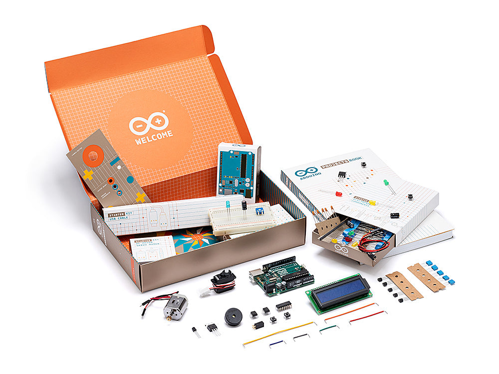
I bought the Arduino Starter Kit K000007 from Abhishek Prabhu of Smapptech Systems Pvt Ltd, an Authorized Distributor for India according to the Arduino website. Abhishek is very knowledgeable in the DIY electronics space and I really liked doing business with him.
The kit has an Arduino UNO board and an Arduino Project Book (English) explaining around 14 projects step-by-step. Some of these projects are also available as Arduino Video Tutorials in YouTube by Massimo Banzi, one of the Co-Founders of Arduino.
All hardware components you need (resistors, capacitors, 16×2 LCD, piezo buzzer, servo motor, DC motor…) to build these projects are already included in the Starter Kit. Arduino IDE (Integrated Development Environment) is open source and can be installed in a computer for writing the code for our Arduino circuit. After saving the code in Arduino IDE, it compiles and downloads the executable code to our Arduino UNO board via a USB cable.
Armed with a new hope and lots of encouragement from my kids, I set out to revisit my old ‘electronics empire!’
An ‘Unstoppable’ Stopwatch!
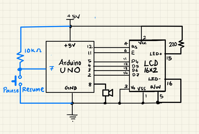
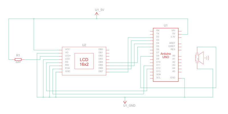
After trying out some circuits from the project book with moderate success, we wanted to do something new, something simple; but something completely of our own. Finally we decided to build a stopwatch using the LCD. The circuit schematics diagram was hand-drawn after referring the pin-outs of Arduino UNO board and other components mentioned in the Arduino Project Book. Our circuit schematics diagram featured a ‘pause/resume’ push button switch and a piezo buzzer that beeps once in every minute.
Wiring the circuit didn’t take much time on a breadboard. On the other hand, it took some time to come up with a working code. After many iterations, the basic functionality was in place and the stopwatch was working properly in MM:SS format up to 59 minutes: 59 seconds.
Eventually the blue colored parts in the above Schematics Diagram were not built. Since there was no Pause/Resume push-button switch, our stopwatch cannot be stopped at all while running!
WARNING: Geeky Things Ahead… You are Free to Skip This and move to the Next Section!
As the external interrupt pins D2 and D3 of the Arduino UNO were used up by the LCD data lines, we couldn’t use those pins for the Pause/Resume push button switch. An alternative attempt on polling the push button switch for its key-press state completely threw off the stopwatch accuracy. So, we were forced to remove the Pause/Resume functionality resulting in an unstoppable stopwatch! Now the stopwatch circuit became an incremental counter up to 59 minutes: 59 seconds. Then It would reset to 00:00 and would start again to count up.
The Pulse Width Modulation (PWM) signal from the Arduino for the piezo buzzer started interfering with the LCD data lines resulting in garbled characters appearing on the screen. This was solved by moving the piezo buzzer wire connection away from the LCD lines to reduce the interference. We also reduced the duration of the ‘beep’ sound of the piezo buzzer from 1 second to 500 milliseconds.
Hours spent on ‘Hours!’
When we tried to display the hours on the LCD in HH:MM:SS format, things went south. The highest value the stopwatch could display was 23 hours: 59 minutes: 59 seconds. Then we hit a roadblock as an elusive bug began to reset the stopwatch while running.
After struggling for hours to figure out the bug, I lost my patience completely. Then I started looking for an onboard debugger or an Arduino simulator that will open up the states and values of variables of the running code in near real time. Then I made an amazing discovery!
TinkerCAD Circuit Simulator for the Rescue
Autodesk’s browser based TinkerCAD has an excellent circuit simulator along with its more popular 3D modelling module. The circuit simulator has a library full of electronics components, micro-controller systems including commercially available Arduino boards. This makes it possible to virtually build and test an electronics system on your computer without buying or assembling the corresponding physical hardware.
And, TinkerCAD is free. You can learn electronics by doing and save money at the same time!
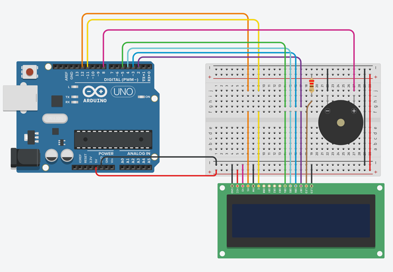
After replicating our stopwatch circuit in the TinkerCAD Simulator, our software code for the circuit was also copied from the Arduino IDE into it. By adding breakpoints, stepping over each lines of code and observing the values stored in different variables, we were able to recreate the bug. Once the problem was identified (a silly mistake in resetting some variables!), finding a solution, and testing the code was really fast. TinkerCAD simulator saves time, too!
The Force Awakens
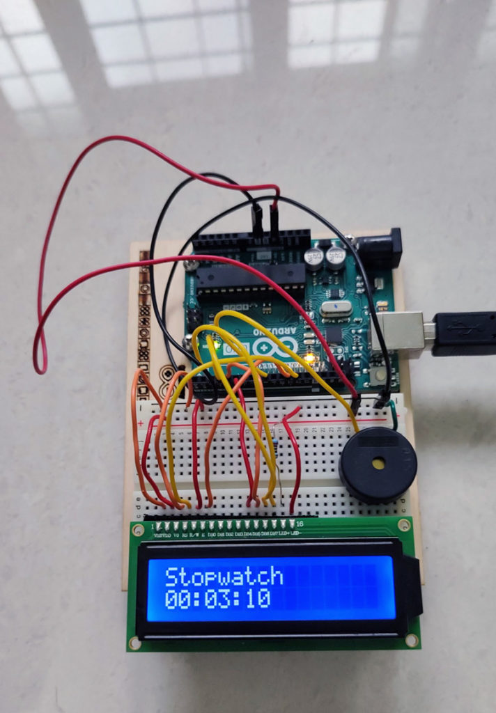
You can take a look at the final version of the stopwatch circuit, the code execution, and the schematics diagram in the TinkerCAD Simulator by clicking here.
My kids are very much excited about this ‘new toy!’ I’m also finding it interesting to design and build something tangible. Before my kids’ schools open in the month of June, we have plans to do more interesting Arduino projects.
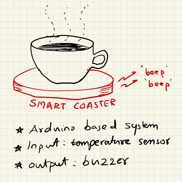
The one that is in our RADAR right now is to build a smart tea cup coaster. It will alert you when the hot tea/coffee cools down to your comfortable, drinkable, preferred temperature. Now you don’t have to burn your mouth and lips by drinking a too hot tea/coffee. You also don’t have to drink a cold tea/coffee because you waited too long for it to cool down. My kids face this problem every day and hence this product idea!
Wish us luck! 😎
We know that others have built the exact same product, some are even using Arduino circuits. But we won’t peek and steal from them. We promise!
UPDATE: Message from my friend who kindled this passion 30 years ago, after reading this Post
Superb! I’m very happy. No corrections are needed in the narrative.
– Shihab
My best wishes and prayers for you…


