I love cars. I like to draw and ‘invent’ new models of cars.
Recently, I started the surface modeling of a car using CATIA — a 3D Engineering software. Today I am attempting to give a ‘crash course’ on making your own cars in CATIA. If some of you started asking questions on this subject, I will be very happy as my mission is accomplished.
You can click on the images for a larger view.
Initial Steps
Here we shall see how to make some awesome surface models in CATIA. The basic approach in CATIA is pretty much similar to the way cars are made in 3ds max or other surface modelers. Some obvious advantages of using CATIA are getting curvature continuity, having a clear construction history etc. Don’t worry of these, if you didn’t understand.
The first step is to choose what we want to model. It can be any product as long as you are clear about its overall form. I started with a particular car model in mind. Making surface models from your own sketches is the best, because you have a pretty clear idea of what you want in the end.
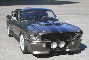
My choice is a 1967 Ford Mustang. I collected enough images from internet to get an idea of the shape, size and the surface of the car.
Backplates


It is important to have good backplates. Search the internet and find some that suit you.
These backplates tell us the relative location of the curves and body features. The importance of good backplate images cannot be stressed enough.
I would like to recommend The-BluePrints.com. It’s an awesome site, with good quality backplates. You can even buy vector blueprints. The JPG ones are free.
How to apply these backplates to CATIA?
Open CATIA and go to START>Shape>Generative Shape Design.
Click on the Sketcher icon and select XY plane. Make a rectangle and hit Exit Sketcher.
The next screen should look like this:
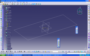
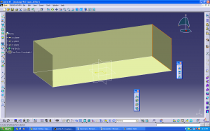
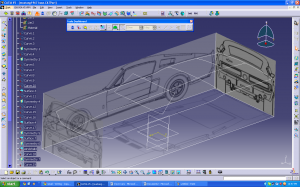
Hit the fill command to fill the sketch you made into a surface. The objective is to get 3 walls like this:
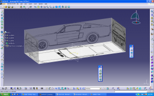
Now we can apply the backplate images and this is what we get:
Please see this link to know this process in detail.
Making our own Car


Now we are ready to start making the car. Switch to START>Shape>Freestyle.
I chose the windshield as the starting point of the modeling. You are free to choose any parts to start with.
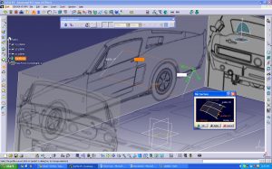
Step 1: Right click on the Compass and select Make XY the privileged plane.
The privilege plane decides what the mouse does. XY privileged option will make the points slide along XY plane when dragged with the mouse.
Now go to the 3d curve button.
This allows us to place control points for the curve we want.
After clicking OK to create the curve, click on the control points button.
This allows us to fine tune the curve as we want. It also allows to move the vertices around and also to create a curve which is symmetrical about the mid plane of the car body. The same option also edits surfaces. Control point dialog box is very useful in surface modeling using CATIA.
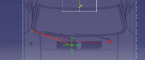
Using the 3d Curve and control point options, I made the bounding curves for the windshield.
Surfaces

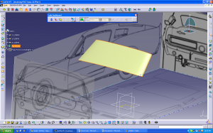
Next step is surface creation. Click on Net surface.
In the dialog box that opens, select the side curves as guides. Hold down CTRL as you select.
Now select the top and bottom curves as profiles.
Don’t forget to hold CTRL to select multiple profiles. Press OK.
Congratulations! You have made your first surface. Yeah!
This surface can be further edited using the control points button.
Surface by surface…
Now you can make curves for the car body and tweak them around. Use your mouse to move them after selecting the points in the control point dialog box.
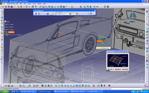
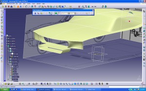
The following screenshot shows the car body with the top.
You can skip this if you don’t understand!
The key to good surfaces are good quality curves. The curves youu get in this method are NURBS, the degree is up to you. The degree of surfaces is limited to 16 in CATIA V5.
Next, to ensure good quality surface rendering, curvature continuity is essential. You can read about it here.
Curvature Continuity

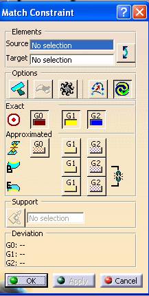
To get curvature continuity in CATIA, click this button.
This button works for cures as well as surfaces. This function joins end points of stranded curves to one another, closes gaps between surfaces. It’s the ‘Fevikwik’ of surfacing!
In Match Constraint dialog box, Source is the surface you want to change and Target is the one you keep as reference. Click on G2.
Now click Apply. Check that the source surface is not moving too much. If you are satisfied, click OK.
The three basic commands of control points, net surface and matching constraints are more than enough to make the car. To give surface fillets, a separate command is there.
My Mustang
I am yet to finish the Mustang. Following is its present state.
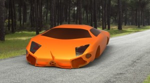
Lamborghini in CATIA
You can click on the images for a larger view.
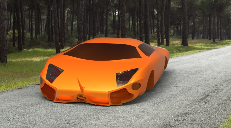
My friend Samarendra Das (aka Agent_Sam) modelled this Lamborghini in CATIA.
Acknowledgments
I would like to thank Samarendra Das for his help. A self taught surface modeler, he is the person who inspired me to become a CATIA car designer.
Further Reading
If you have any doubts, feel free to add them as comments below.










Nice work…can’t wait to see when its finished.
Would be Inspiring work for newbees n catia freaks..
Goodone Kishore n Antz
nice
the work is amazing.
but i am having problem in making the control curves.
when i make 3-d curve , the all control curve lies on the sketch itself instead of plane.
so i end up making a 2d drawing…
hey could you plz upload the final 3d model of the car.It would be very helpful!!
superb work sir !!!!!!
great that u r sharing ur idea’s with catia learning people.
sir I am learning catia but I am not able to read a design correctly and in exact time. so how can I solve this drawback, my speed to make a part or model is very slow so please sir suggest me what I have to do ?
I will be grateful to u
thank u
rohit narayan
Dear Rohit
Speed will come with time and practice. One thing I can suggest is to plan your approach before making Cars (or any other models) in CATIA. A good method is to always use very simple Feature-based commands, that way your model will be easy to edit and modify.
i want to design audi r 8 using surface modelling.
in creo it is possible?